Hi Community!
A volume unit meter, often known as a VU meter, is a device used in music equipment to display the intensity of an audio stream (loudspeaker, mic, electric guitars, amps, etc.). It is used to visualize analog signals in particular. We’ll make a basic VU meter with the LM3914 dot/bar display driver IC in this project. The LM3914 is an analog LED driver IC, which means it can control (on or off) 10 LEDs using an analog input voltage. This IC eliminates the requirement for a microcontroller and minimizes the amount of hardware needed to control 10 LEDs. The input voltage of the LM3914 can range from 3 to 18 volts. The IC has two modes of operation: DOT and BAR, and multiple ICs can be cascaded to control up to 100 LEDs. These ICs are often used in visual alarms and other metering or monitoring applications because the LEDs can be regulated without flickering and function flawlessly with equal brightness. This can be used together with an audio amplifier to make the circuit look better and have a good presentation!
Materials
- • R1—10KΩ
- • R2—3.9KΩ
- • R3—2.9KΩ
- • C1, C2-1uF
- • IC1—LM3914
- • LEDs-5mm LED (blue, green, red) (10)
- • D1, D2-1N4004
- • S1-Toggle Switch
- • Power Supply or 9V Battery
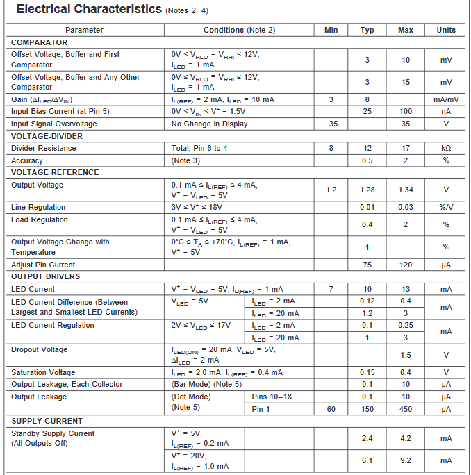
IC Datasheet Information
- • Drives LEDs, LCDs or vacuum fluorescents
- • Bar or dot display mode externally selectable by user
- • Expandable to displays of 100 steps
- • Internal voltage reference from 1.2V to 12V
- • Operates with single supply of less than 3V
- • Inputs operate down to ground
- • Output current programmable from 2 mA to 30 mA
- • No multiplex switching or interaction between outputs
- • Input withstands ±35V without damage or false outputs
- • LED driver outputs are current regulated, open-collectors
- • Outputs can interface with TTL or CMOS logic
- • The internal 10-step divider is floating and can be referenced to a wide range of voltages

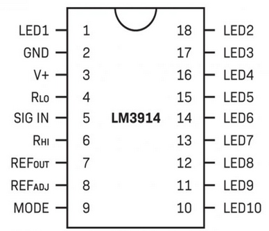
IC Datasheet Pinout
- Pin1: 1 and 10 to 18 - LEDs (1-10) - 10 LEDs pinout to be controlled
- Pin2: - V-/GND - Ground
- Pin3: - V+/Vcc - Chip Supply Voltage (3-18V)
- Pin4: - RLO - Low level voltage for potential divider
- Pin5: - SIGNAL - Input AC signal
- Pin6: - RHI - High Level voltage for potential divider
- Pin7: - REF(OUT) - Output Reference Voltage for LED current limiting
- Pin8: - REF(ADJ) - Adjust pin for voltage reference
- Pin9: - MODE - Mode selection pin (DOT/BAR)

Applications of the IC
The applications of the LM3914 amplifier circuit include the following.
- • This IC is most typically utilized in the music business for live music production and recording techniques.
- • It may be reverse-engineered to function as a power level indicator for a variety of energy-storage devices, including batteries and dry cells
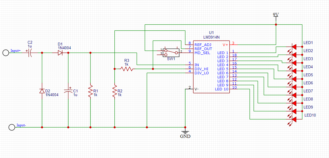
Schematic of the LM3914 VU Meter

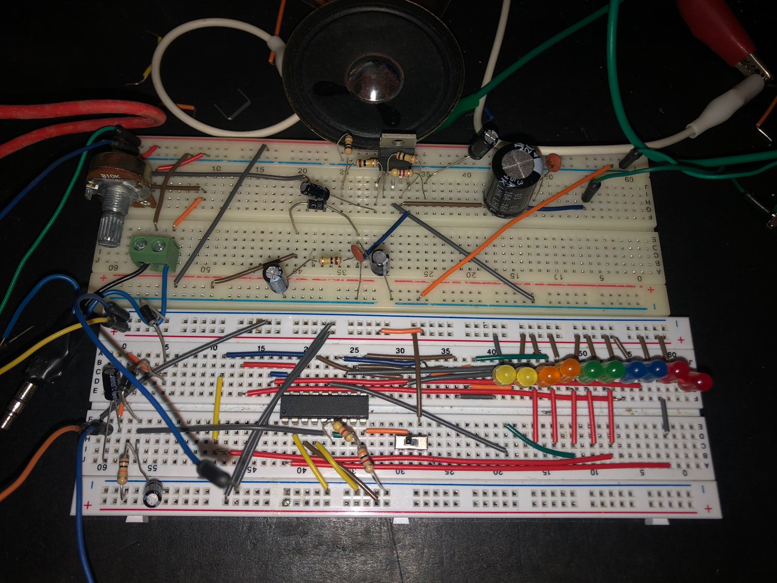
Schematic on the breadboard

Make sure to check our full document about audio amplifiers where i make 5 audio amplifier circuits!
Audio Amplifier Circuits