Hi Community!
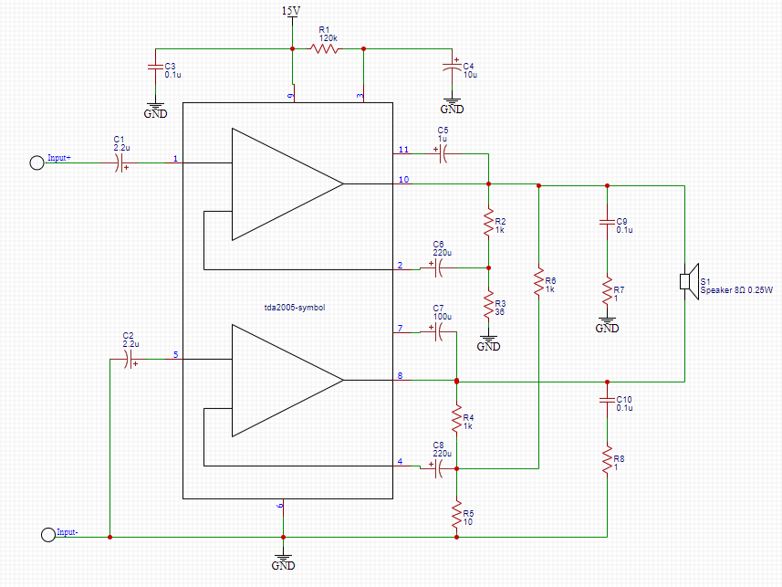
Two op-amps are included in the TDA2005’s internal structure. In this circuit, we use a bridge model to connect them. There is a lot of output power in this shape, more than in others. If you utilize a mono system, you will get a 10 watt output. However, the power of the bridge system is 20-30 watts. An output speaker and a power supply are also present. Because it is a power amplifier for a car radio, the power supply voltage is 12 volts 14.4 volts. Its importance is that it can respond to frequencies ranging from 35 Hz to 15 KHz. We have a good understanding of the TDA2005 amplifier circuit diagram’s features. We’ll wait and see how it goes.
Materials
- • R1—120KΩ
- • R2—1KΩ
- • R3—36Ω
- • R4—1KΩ
- • R5—10Ω
- • R6—1KΩ
- • R7—1Ω
- • R8—1Ω
- • C1-2.2uF
- • C2-2.2uF
- • C3-0.1uF
- • C4-10uF
- • C5-100uF
- • C6-220uF
- • C7-100uF
- • C8-220uF
- • C9-0.1uF
- • C10-0.1uF
- • IC1—TDA2005
- • SP1—8 Ω 0.25W speaker
- • Power Supply or 9V Battery
IC Datasheet Information
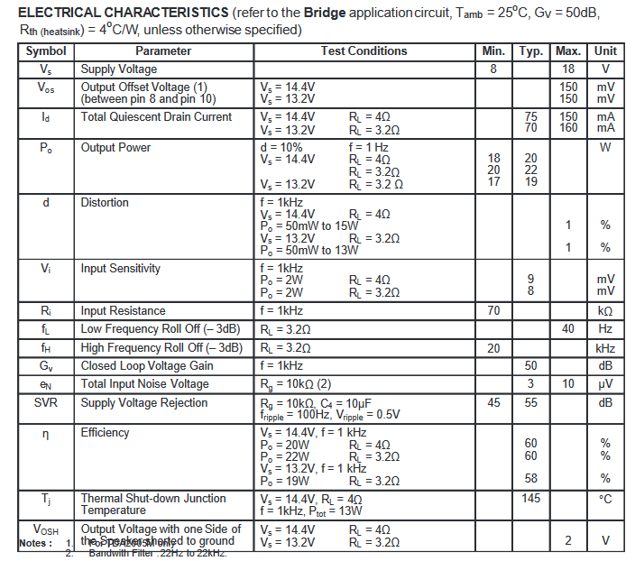
- • High Output Power
- • High reliability of the chip and package with additional complete safety during operation thanks to protection against: output DC and AC short circuit to ground, overrating chip temperature, load dump voltage surge, very inductive loads.
- • Flexibility in use: bridge or stereo booster amplifiers with or without boostrap and with programmable gain and bandwidth.
- • Space and cost saving: very low number of external components, very simple mounting system with no electrical isolation between the package and the heatsink (one screw only).

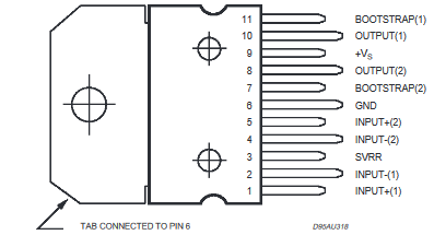
IC Datasheet Pinout
- Pin1: Input + 1 - Non-Inverting Input of amplifier 1
- Pin2: Input - 1 - Inverting Input of amplifier 1
- Pin3: SVRR - Supply Voltage Rejection Ratio
- Pin4: Input - 2 - Inverting Input of amplifier 2
- Pin5: Input + 2 - Non-Inverting Input of amplifier 2
- Pin6: Ground - The ground is connected to this pin
- Pin7: Bootstrap 2 - Amplifier 2 bootstrap capacitor
- Pin8: Output 2 - The output of amplifier 2
- Pin9: + Vs - Positive Power Supply
- Pin10: Output 1 - The output of amplifier 1
- Pin11: Bootstrap 1 - Amplifier 1 bootstrap capacitor

Applications of the IC
The IC TDA2005 is one of the most essential integrated circuit in the audio area, and it's found in the applications below.
- • Employed in Car radio
- • Used in Microphone amplifiers
- • Used in audio power amplifiers
- • Incorporated in Woofer amplifiers
- • Used in Music players
Schematic of the TDA2005 Audio Amplifier

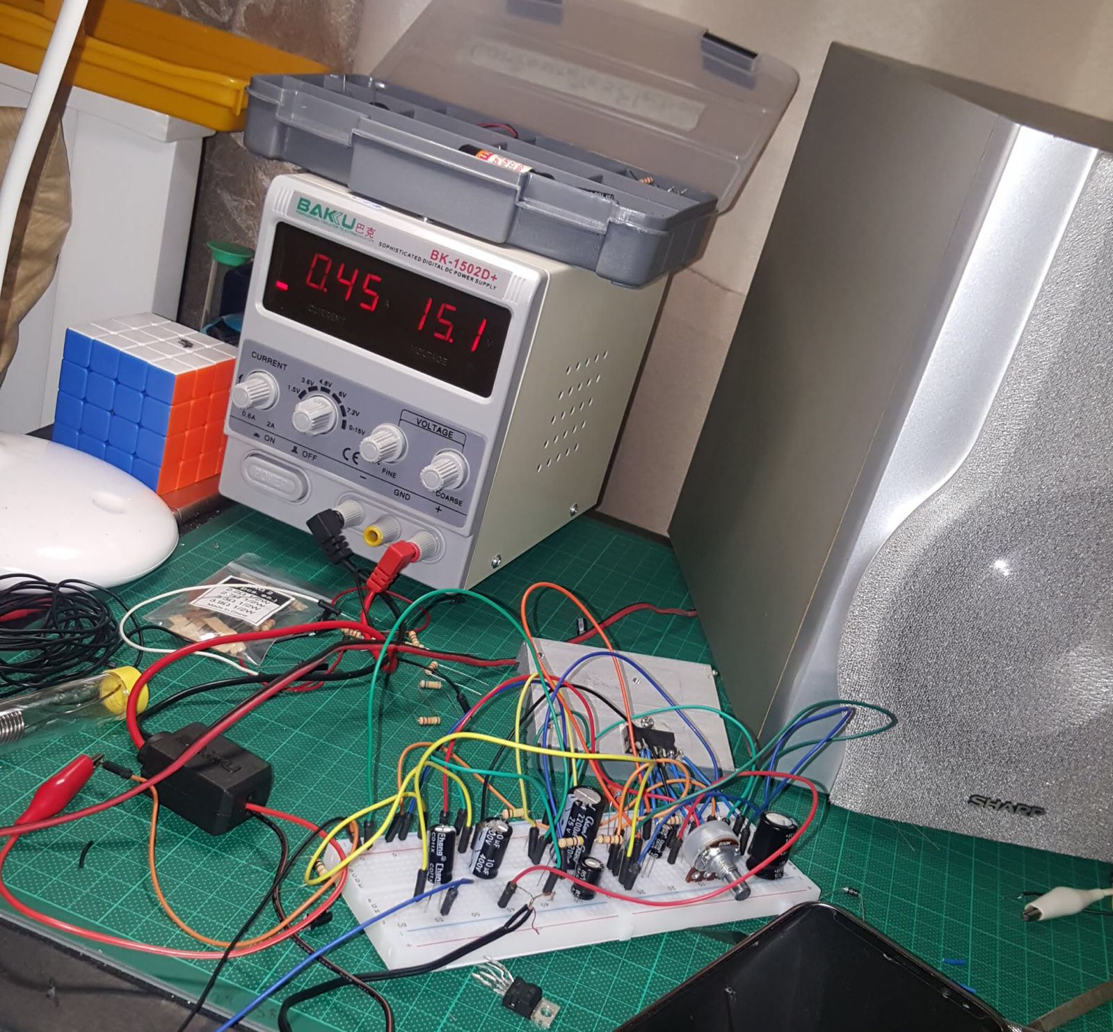
Schematic on the breadboard

Make sure to check our full document about audio amplifiers where i make 5 audio amplifier circuits!
Audio Amplifier Circuits