Inductance Measurement
The tendency of an electrical conductor to resist a change in the electric current passing through it is known as inductance. A magnetic field is created around a conductor by the flow of electric current. The field strength is proportional to the current magnitude and follows any variations in current. Any change in magnetic field via a circuit generates an electromotive force (EMF) (voltage) in the conductors, according to Faraday's law of induction, a process known as electromagnetic induction. The induced voltage formed by the changing current acts to counteract the current change. Lenz's law states this, and the voltage is referred to as back EMF.
Materials for Inductance Measurement
- • Arduino Uno
- • Cables and Breadboard
- • R1-1KΩ
- • R2-220Ω
- • D1-1N4004
- • C1-1uF Ceramic Capacitor
- • IC1-LM358
- • L1-Any inductor to measure
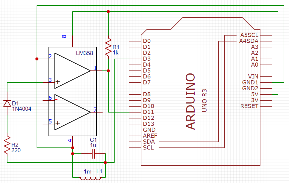
Schematic for Inductance Measurement
To test this circuit we just need to use any inductor.

Code for Capacitance Measurement
#define ChargePin 3
#define PulseInPin 11

double capacitance, inductance, pulse, frequency;

void setup(){
    Serial.begin(9600);
    pinMode(PulseInPin, INPUT);
    pinMode(ChargePin, OUTPUT);
    delay(200);
}

void loop(){
    digitalWrite(ChargePin, HIGH);
    delay(5);
    digitalWrite(ChargePin,LOW);
    delayMicroseconds(100);
    pulse = pulseIn(PulseInPin,HIGH,5000);

    if(pulse > 0.1)
    {
        capacitance = 1.E-6;
        frequency = 1.E6/(2*pulse);
        inductance = 1.0/ (capacitance*(frequency*frequency)*4.0*(3.14159*3.14159));
        inductance = inductance*1E6;
        Serial.print("Inductance uH:");
        Serial.println( inductance );
        delay(10);
    }
    delay(1000);
}
To see the results you need to check the serial monitor!