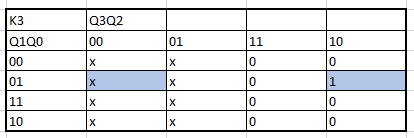


Next, all the algebraic functions obtained by the K maps are presented in order:

We now make the circuit with logic gates:


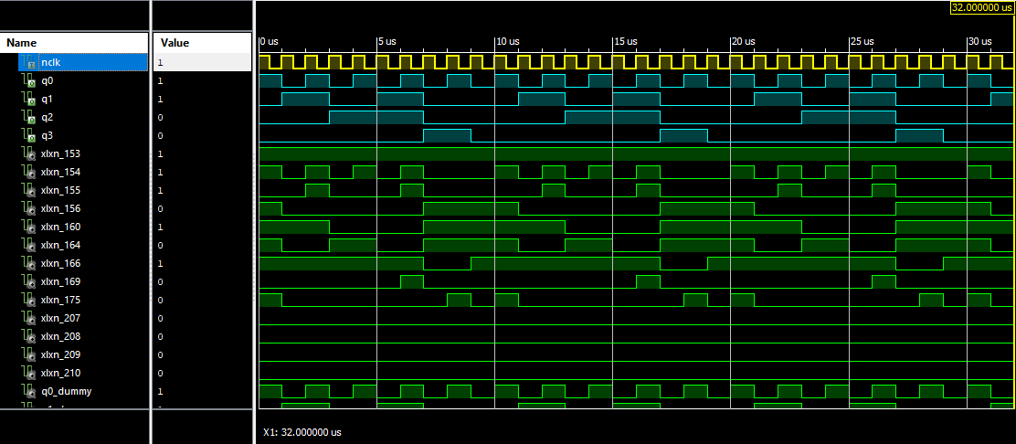
Next, the same test will be done, only by adding the clock at the input of the circuit, the difference in the values of the period will be seen.


The behavior of the circuit could be perfectly appreciated and it was seen how the flip flops perform the specified function thanks to the truth table. The difference was also appreciated when adding the clock and not adding and only forcing the clock, when simulating it is nice to see the period a little more displaced but when uploading it to the card it must be done correctly with the period determined
Circuit 7 Segments XS3
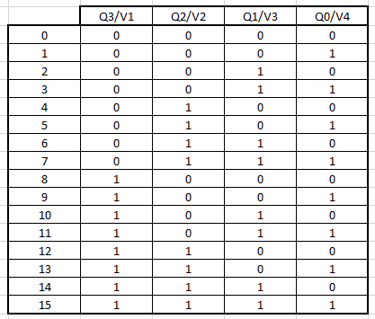
As in the last section, we must go through the construction of this circuit step by step for its understanding, this circuit is based on showing the numbers from an Excess to 3 on a 7-segment display, this from theory tells us that if the input is 0 the output should give us a 3, if 1 enters, the output will be a 4 and so on until reaching 9, after reaching 9 a condition is given that from this number will begin to show the letters H and U duly interspersed, as this circuit is next to our 0-9 counter, only HUH will be displayed, since after this the circuit will reset and return to the original state counting from 0 to 9. First, the truth table is made:

It can be seen that in the name of each column of the table is the output/input of the corresponding circuits, when Qn means the output of the previous circuit and Vn the input of the 7-segment circuit.

You can clearly see the outputs from A to G, this is thanks to the 7-segment nomenclature as shown below, if a letter has 1 it means that that section of the 7-segment will be illuminated, while if a 0 appears it will be off.

The creation of the K maps to obtain the algrebraic functions begins:


